Grúas aéreas para plantas de conversión de residuos en energía: guía esencial de configuración y selección
Tabla de contenido
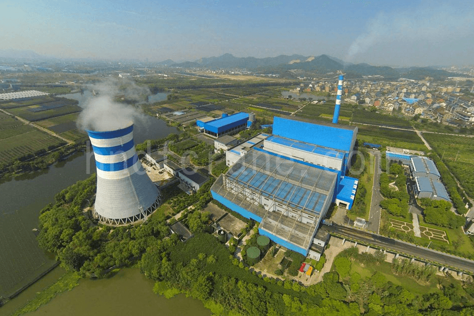
Las grúas puente desempeñan un papel crucial en las plantas de conversión de residuos en energía, ya que incluyen la manipulación de materiales, la instalación de equipos y el mantenimiento. La configuración adecuada de estas grúas no solo mejora la eficiencia operativa de la planta, sino que también garantiza la seguridad y la estabilidad de la producción. Basado en años de práctica de ingeniería, este artículo explora la configuración y el papel de las grúas puente de las plantas de conversión de residuos en energía, y brinda información valiosa para el diseño y el funcionamiento de dichas instalaciones a nivel mundial.

I. Configuración básica de las grúas en plantas de conversión de residuos en energía
La escala de las plantas de conversión de residuos en energía varía significativamente, desde plantas pequeñas con una sola línea que procesa 300-500 toneladas por día (t/d) hasta plantas grandes con 4-6 líneas que procesan 750-850 t/d por línea. La Tabla 1 resume las configuraciones y los montajes de las grúas en los proyectos existentes. Los datos de elevación se refieren a la elevación superior del riel, con el volumen efectivo de la cuchara de agarre indicado entre paréntesis.
| No. | Grúa | Tipo de grúa | Modo de funcionamiento | Ubicación de instalación | Capacidad de elevación (cuchara de agarre/m³) / t | Deber de trabajo | Observaciones |
|---|---|---|---|---|---|---|---|
| 1 | Grúa recogedora de basura | Grúa aérea con pinza de doble viga | Continuo, 24 horas/día (24 h/d) | Directamente encima del pozo de desechos, elevación 25–35m | 11(6.3),12.5(8),18(10),20(12) | A8 | No menos de dos unidades, con una de repuesto; no se requieren características a prueba de explosiones |
| 2 | Grúa recogedora de cenizas | Grúa aérea con pinza de doble viga | Continuo, 8~12 h/d | Directamente encima del pozo de escoria, elevación 7-12m | 8(3.2),10(4) | A6~A8 | |
| 3 | Grúa de instalación y mantenimiento de turbinas | Grúa aérea con gancho de doble viga | Intermitente | Dentro de la sala de turbinas, elevación 13-15m | 20/5,25/5,32/5,50/10 | A3 | |
| 4 | Grúa de mantenimiento integral de salas de bombas | Grúa suspendida monorraíl eléctrica | Intermitente | Dentro de la sala de bombas integral, elevación 6–9m | 2~3 | A3 | |
| 5 | Grúa de mantenimiento para almacenamiento temporal de cenizas volantes | Grúa suspendida monorraíl eléctrica | Intermitente | Mantenimiento de equipos dentro de la sala de almacenamiento temporal de cenizas volantes, elevación 6–9m | 2~3 | A3 | |
| 6 | Mantenimiento de taller de polipastos eléctricos | Grúa suspendida monorraíl eléctrica | Intermitente | En la parte superior del taller, elevación 6-8 metros. | 2~5 | A3 | |
| 7 | Polipasto eléctrico de mantenimiento para colector de polvo de mangas | Grúa suspendida monorraíl eléctrica | Intermitente | Ubicado en la parte superior del colector de polvo de la cámara de mangas. | 1~3 | A3 | |
| 8 | Mantenimiento de grúas recogedoras de basura Polipasto eléctrico | Grúas monorraíl eléctricas | Intermitente | Directamente encima de la grúa recogedora de basura, elevación 32-40 metros | 3~5 | A3 | |
| 9 | Mantenimiento de ventiladores de tiro inducido Polipasto eléctrico | Grúas monorraíl eléctricas | Intermitente | Directamente encima del ventilador de tiro inducido, elevación 7-10 metros | 5~10 | A3 | |
| 10 | Mantenimiento de bombas de agua de alimentación Polipasto eléctrico | Grúas monorraíl eléctricas | Intermitente | Directamente encima de la bomba de agua de alimentación en la sala de turbinas, elevación de 6 a 8 metros | 3~5 | A3 | |
| 11 | Mantenimiento de ventilador de aire primario Polipasto eléctrico | Grúas monorraíl eléctricas | Intermitente | Directamente encima del ventilador de aire primario en el taller de incineración, elevación 6-8 metros | 2~5 | A3 | |
| 12 | Polipasto eléctrico para mantenimiento de sala de compresores | Grúas monorraíl eléctricas | Intermitente | En la parte superior de la sala de compresores, elevación de 6 a 8 metros. | 1~3 | A3 | |
| 13 | Polipasto eléctrico para mantenimiento de calderas | Grúas monorraíl eléctricas | Intermitente | En la parte superior de la caldera, por encima de la elevación de la viga principal de la caldera. | 2~5 | A3 | |
| 14 | Polipasto eléctrico de mantenimiento para torre de desacidificación | Grúas monorraíl eléctricas | Intermitente | Por encima de la elevación de la parte superior de la torre de desacidificación | 1~3 | A3 | |
| 15 | Polipasto eléctrico para mantenimiento de bombas de lixiviado | Grúas monorraíl eléctricas | Intermitente | Por encima del tanque de lixiviados, elevación -2 a -5 metros | 1~3 | A3 | Se requiere una configuración a prueba de explosiones |
Tabla 1: Principales parámetros técnicos de las grúas en plantas de conversión de residuos en energía
II. Funciones y configuraciones de las distintas grúas
Grúa aérea con pinza de doble viga
(1)Grúa para manipulación de residuos

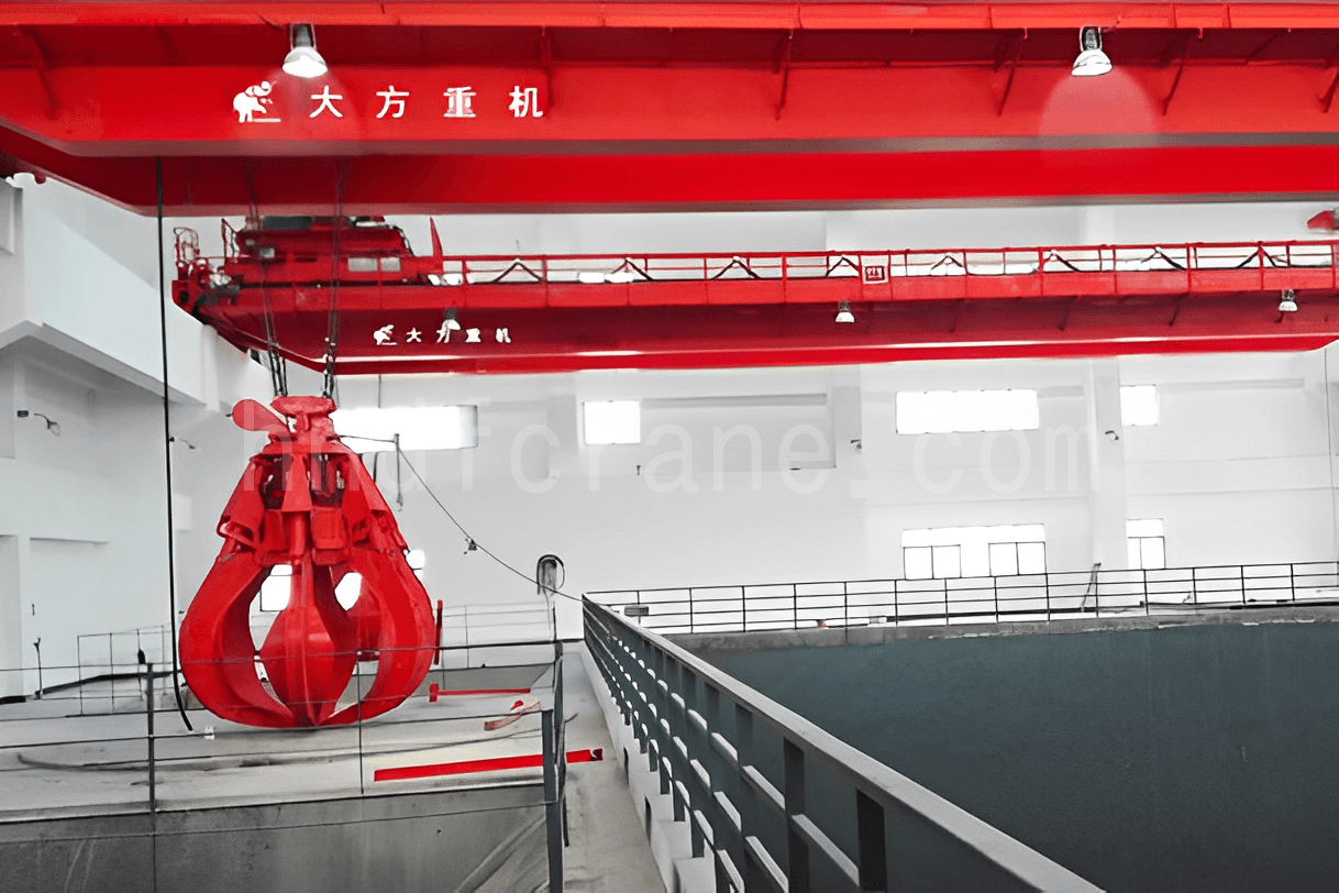
La función de la grúa de manipulación de residuos El objetivo de la grúa de recogida de basuras es recoger, apilar, volcar y alimentar los residuos dentro del pozo de residuos. Se instala por encima del pozo de residuos, con el punto más bajo de la grúa a una distancia mínima de 2 metros del nivel de la tolva de alimentación de residuos. La sala de control de la grúa de recogida de basuras se encuentra frente a la tolva de residuos o al costado de la misma. La grúa de recogida de basuras y el incinerador deben funcionar simultáneamente para garantizar el funcionamiento seguro y estable de la planta de incineración; de lo contrario, interrumpirán la alimentación al incinerador, lo que podría provocar el cierre de toda la planta. Por lo tanto, la grúa de eliminación de basuras es una pieza fundamental del equipo de la planta de incineración, que requiere una precisión, estabilidad y fiabilidad extremadamente altas. Su clase de servicio debe cumplir con las normas A8 y debe configurarse con una unidad activa y una de reserva.
Además, teniendo en cuenta el duro entorno (por ejemplo, húmedo, ácido, que contiene gases nocivos como CH4 y H2S), es fundamental utilizar componentes maduros y estables para la cuchara, los sistemas hidráulicos y los componentes eléctricos. Según años de experiencia operativa, la concentración de gases inflamables y explosivos en el área donde opera la grúa de manipulación de residuos no suele ser alta y, en la mayoría de los casos, no se requieren configuraciones a prueba de explosiones.
(2) Grúa recogedora de cenizas
La función de la grúa de recogida de cenizas es trasladar la escoria descargada desde el incinerador hasta los vehículos de transporte. En comparación con la grúa de recogida de basura, los requisitos de rendimiento de la grúa de recogida de cenizas son relativamente menores, ya que no necesita funcionar en sincronía con el incinerador. Teniendo en cuenta el volumen limitado del pozo de escoria, se requiere que el tiempo máximo para resolver cualquier avería en el pozo de escoria no supere un día. La sala de control de la grúa de recogida de cenizas suele estar situada en el lateral o en el extremo del pozo de escoria, y algunas plantas de incineración utilizan un control remoto para su funcionamiento.
La clase de servicio de la grúa de recogida de cenizas es generalmente inferior a la de la grúa de recogida de basuras, siendo suficiente la A6. Sin embargo, también se debe considerar la configuración real de la unidad y del contenedor de almacenamiento de escoria. En general, las plantas de incineración con más de dos líneas de incineración deben utilizar una clase de servicio de A7 o A8. Para plantas de incineración grandes con cuatro líneas de incineración, considerando el gran ancho del área de almacenamiento de escoria, se deben utilizar dos grúas de recogida de cenizas.
Grúa aérea de doble viga

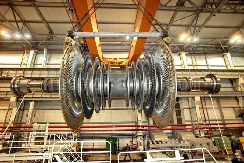
El puente grúa birraíl Se refiere a la grúa de instalación y mantenimiento de turbinas (en adelante, grúa de turbina). Su función principal es la instalación y el mantenimiento de turbinas y generadores. A diferencia de la grúa recogedora de basura y la grúa recogedora de cenizas, la grúa de turbina solo se utiliza después de que la planta esté operativa. Debido al gran tamaño y la masa de las unidades de turbina-generador, generalmente se transportan a la planta de conversión de residuos en energía en partes separadas de la planta de fabricación. Luego, la grúa de turbina se utiliza para levantar e instalar los componentes de la turbina y el generador. Después de la instalación, la grúa de turbina debe usarse regularmente para el mantenimiento y la inspección de la turbina y el generador. La grúa debe funcionar a plena capacidad al menos dos veces al año (2 veces/a).
Grúa suspendida monorraíl eléctrica
La grúa monorriel suspendida eléctrica es la principal responsable del mantenimiento y la inspección de la sala de bombas integral, la sala de almacenamiento temporal de cenizas volantes, el taller y el propio colector de polvo de la cámara de filtros. El diseño de estas salas requiere que el polipasto tenga funciones de elevación, carro y movimiento de grúa. Por ejemplo, en el colector de polvo de la cámara de filtros, los componentes como los limpiadores de cenizas y las jaulas de bolsas deben elevarse y colocarse a lo largo de toda la superficie de trabajo. El polipasto debe poder alcanzar todas las áreas del espacio de trabajo y el polipasto de mantenimiento debe usarse al menos dos veces al año (2 veces/a).
Grúas monorraíl eléctricas
La pista del eléctrico grúa monorriel Es relativamente simple y se utiliza principalmente para levantar y transportar equipos pesados fijos, como ventiladores, bombas y otra maquinaria giratoria. La capacidad máxima de elevación no supera las 10 toneladas y la mayoría requiere movimiento a lo largo de una vía unidireccional, mientras que algunos solo necesitan la función de elevación. Es importante tener en cuenta que en algunas áreas puede haber gases inflamables y explosivos como H2S, CO y NH3, requiriendo el uso de motores a prueba de explosión.
III. Métodos de selección de grúas para plantas de conversión de residuos en energía
En las plantas de conversión de residuos en energía, hay varios conjuntos de grúas, cada uno de los cuales varía significativamente en tipo, capacidad de elevación, requisitos técnicos y diseño. Los elementos 1 a 3 de la Tabla 1 generalmente representan las configuraciones estándar para plantas de conversión de residuos en energía, mientras que otros equipos se determinan en función de la escala de la planta, la configuración del equipo y los requisitos del propietario.
Las grúas se pueden dividir en equipos operativos y equipos de mantenimiento según su función. Tanto la grúa de recogida de basura como la grúa de recogida de cenizas se incluyen en los equipos operativos, que requieren horas de funcionamiento diarias. En particular, la grúa de recogida de basura debe funcionar de forma continua con precisión y estabilidad, y son necesarios al menos dos juegos de grúas. La mayoría de los proyectos también requieren una grúa de recogida de emergencia adicional para garantizar que las operaciones no se detengan debido a un mal funcionamiento de la grúa de recogida de basura. Las grúas de mantenimiento se utilizan con menos frecuencia y sus requisitos ambientales varían.
(1) La capacidad máxima de elevación de la grúa de recolección de basura está determinada por la configuración de la unidad del proyecto, la capacidad de procesamiento y el diseño del pozo de desechos. Con base en diseños de proyectos anteriores, las capacidades de elevación y los volúmenes de las cucharas de recolección de basura y cenizas se resumen en la siguiente tabla.
| Escala de procesamiento | Grúa de basura / Grúa de cenizas | |||
|---|---|---|---|---|
| Capacidad total de procesamiento (t/d) | Número de líneas de incineración | Capacidad de elevación (t) | Volumen del balde de agarre (m³) | Número de unidades |
| ≤600 | ≤2 | 11/8 | 6.3/3.2 | 2/1 |
| 600 | ≤3 | 12.5/8 | 8/3.2 | 2/1o2 |
| 1200 | 2≤líneas de incineración≤3 | 18/8 | 10/3.2 | 2/2 |
| 1800 | 2≤líneas de incineración≤4 | 18/10 | 10/4 | 3/2 |
| 2400 | ≤4 | 18/10 | 10/4 | 4/2 |
| 2400 | ≤4 | 20/10 | 12/4 | 3/2 |
(2) La capacidad de elevación de la grúa de turbina está relacionada con el peso máximo de un solo componente durante la descarga e instalación del generador. Según la experiencia acumulada, para las unidades de conversión de residuos en energía con una capacidad inferior a 30 MW y menos de 3 unidades, generalmente se selecciona una sola grúa de turbina. Cuando el número de unidades es igual o superior a 3, puede ser aconsejable elegir dos grúas de turbina (una grande y otra pequeña).
(3) La capacidad de elevación de otras grúas de mantenimiento (elementos 4 a 15 de la Tabla 1) depende del peso máximo del equipo que se está reparando. Los factores que se tienen en cuenta al determinar la necesidad de un polipasto varían:
- El peso máximo del ventilador de aire primario y del ventilador de tiro inducido está estrechamente relacionado con la capacidad de procesamiento de cada horno. Esto se debe a que el incinerador y el ventilador funcionan de manera unitaria: cuanto mayor sea la capacidad de procesamiento de un solo incinerador, mayores serán los requisitos de aire y de escape, lo que a su vez aumenta el tamaño y el peso del equipo de ventilación. Según la experiencia en proyectos de ingeniería, se recomienda instalar polipastos de mantenimiento para los ventiladores de tiro primario e inducido asociados con incineradores que procesan más de 600 t/d.
- La necesidad de polipastos de mantenimiento para bombas de agua de alimentación y compresores no está directamente relacionada con la capacidad de procesamiento. La decisión se basa en el peso máximo del equipo.
- Otros polipastos, como los utilizados en torres de desacidificación, colectores de polvo y superficies de calderas, suelen ubicarse a grandes alturas para evitar caídas y garantizar la seguridad de los trabajadores.
- La bomba de lixiviado está ubicada en un espacio sellado lleno de humedad, calor y gases nocivos, lo que hace que la adición de un polipasto de mantenimiento sea útil para reducir la carga de trabajo y mejorar la seguridad del personal de mantenimiento.
En general, la configuración de las grúas de mantenimiento de esta gama es similar a la de otras plantas industriales (como plantas de tratamiento de aguas residuales, centrales térmicas, plantas químicas y acerías). El objetivo principal es satisfacer las necesidades de mantenimiento de los equipos, minimizar el tiempo de mantenimiento y reducir la intensidad de la mano de obra. Al seleccionar grúas pequeñas para estas aplicaciones, las características de las plantas de conversión de residuos en energía no afectan significativamente la elección de la grúa. Los ingenieros pueden configurar las grúas de acuerdo con los estándares nacionales o industriales pertinentes y las condiciones del sitio.
Referencia: Configuración de grúas para plantas de conversión de residuos en energía
Envíe su consulta
- Correo electrónico: sales@hndfcrane.com
- WhatsApp: +86-191 3738 6654
- Tel: +86-373-581 8299
- Fax: +86-373-215 7000
- Dirección: distrito industrial de Changnao, ciudad de Xinxiang, provincia de Henan, China


